PV system design calculator with battery backup
Instructions on using the calculator
- The PV system design calculator calculates the output power requirements, number of panels, number of batteries, and all the rest of the outputs dynamically.
- There are various loads listed on the calculator whose number can be increased to increase or decrease the total load. This will change the number of panels and PV system design.
- There is an option of balance power that can be used to match the power of loads to actual conditions. This power can be taken in positive or negative.
- All values except output can be changed. However, temporary values are added to benefit the user.
- It is tried to keep the inputs of the PV system design calculator to the minimum in order to avoid confusion.
PV system design calculations
The design of a grid-tied PV system firstly requires the calculation of the overall load that is needed to be supplied by the installation. This load is calculated in the first input section of the calculator. In equation form, this calculation is represented by the following Eq. 1, which calculates the total energy required by the loads in Wh.
where xi is the number of similar appliances, Pi is their required power, and ti is the time for which they are turned on. Next, we need to calculate the power required in W to design the system. For this purpose, we need to divide Eq. 1 by peak sunlight hours (PSH) and the efficiency (ηPV) of the PV system.
The peak sunlight hours (PSH) are the total number of sunlight hours where maximum irradiance of 1000 W/m2 is attained at a given place. The sunlight for which the panels are designed is 1000 W/m2, but this amount of sunlight is not achieved all the time. The PSH provides an estimate of how many hours where irradiance from the sun was received and how the average of these hours corresponds to 1000 W/m2. That is why PSH is sometimes referred to as average sun hours. The efficiency in Eq. 2 incorporates the losses due to the inverter, charge controller, and cable losses.
In order to calculate the number of panels (np), the power from Eq. 2 can be divided by the power rating (PP) of the chosen panel in Eq. 3.
To find the number of batteries (NB) we need to find the efficiency of the battery (ηB), the days of autonomy needed (D), the voltage of the battery (V), and the depth of discharge of the batteries (DoD). The days of autonomy refer to the power that is needed to be supplied by the system when there is no availability of the grid (particularly suitable for standalone systems). The depth of discharge refers to the percentage by which the battery can be discharged. This solely depends on the owner of the PV system. If batteries are discharged more, their life span will decrease. We can get Eq. 4 from Eq. 1.
The batteries should be attached in parallel unless specific voltage is required. Usually voltage of batteries are rated at 12V and therefore the designed battery bank should have a voltage that is multiple of 12.
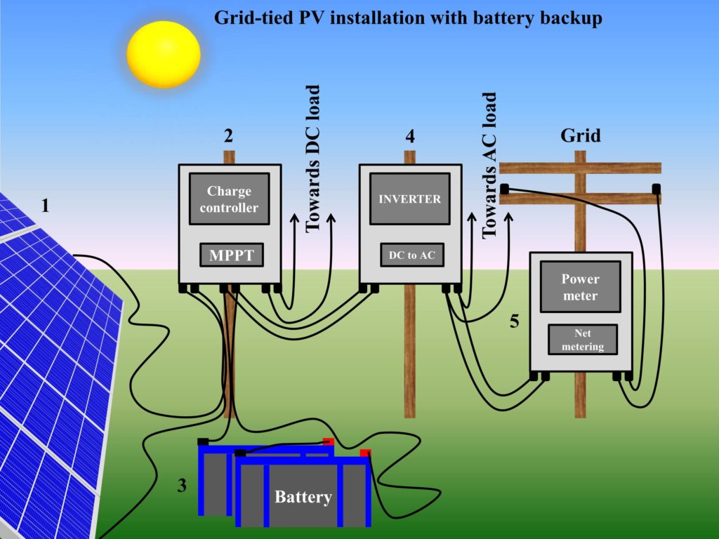
The charge controller and inverter should have a power rating higher than the power of the designed PV system and must be able to sustain the current of the PV panels. In recent PV system installations, the function of the charge controller (maximum power point tracking and voltage regulation between the battery bank and the system) is also governed by inverters, which makes the use of the charge controller redundant. Therefore, only an inverter is required in modern PV system installations. A depiction of grid-tied PV installation with battery backup is shown in Fig. 1.


Great idea. I must assume on it completely.