Parametric Sweep tool
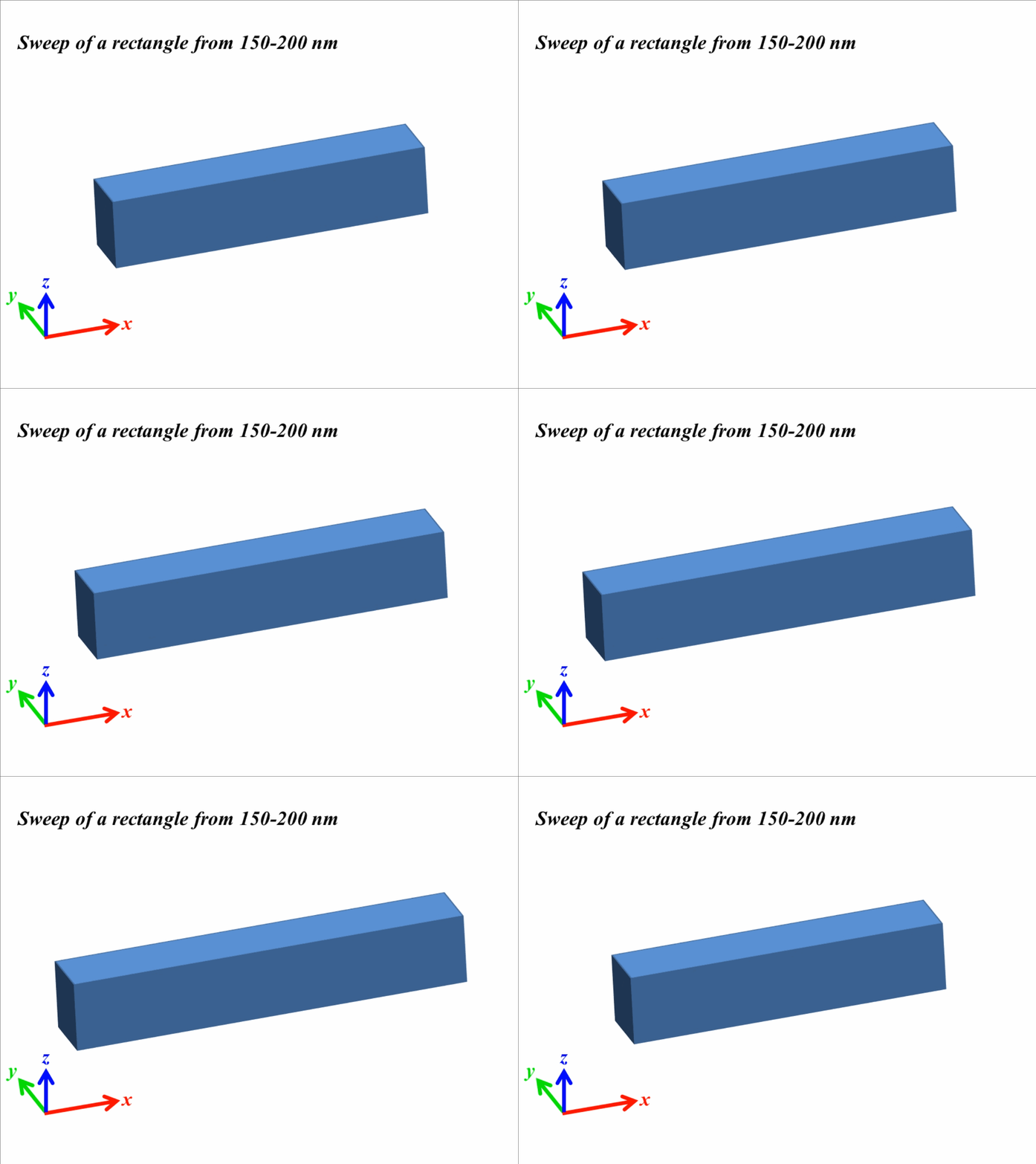
The simulation tools used to simulate 3D nanostructures (or metamaterials/metasurfaces) usually come with a built-in operation of parametric sweep (or simply sweep). A parametric sweep, as evident by its name, sweeps a particular parameter or a set of parameters to evaluate the results. A parametric sweep tool is probably the most important tool after the design of the nanostructure is complete. This tool saves time as it changes the different design dimensions and calculates the results by itself. A range of the parameter is provided with steps or the number of points that are needed to be evaluated in the given range. For example, if we need to change the length of a rectangle from 150 nm to 200 nm, and calculate the results with every 10 nm increase in length, we can run a sweep with a min length of 150 nm and a maximum length of 200 nm with 6 number of points. A depiction of this parametric sweep is shown with a rectangle in Fig. 1.

For the above mentioned sweep, the software will calculate the desired results results at 6 points from 150-200 nm with 10 nm interval.
Uses of paramteric sweep
- The sweep will save time of the user as it will automatically take the change the parameters and run the simulations against the desired results.
- Sweeps can be used to optimize a structure. The design parameters of the structure are swept between minimum and maximum dimensions and those design dimensions can be selected that give the maximum of the desired results.
- Another core aspect of the sweep is their ability to give phase of the electric field. Sweeps can be used to calculate the relative phase of transmitted/reflected electric field for the structure at one interval of a sweep to structure at another interval. For example given in Fig. 1, sweep can be employed to find the phase of transmitted/reflected electric field at 150 nm, 160 nm, 170 nm, 180 nm, 190 nm, and 200 nm. Without one point as a reference, some software cannot calculate phase.
Advanced topics for sweeps
NEsted parametric sweeps
A nested sweep is a sweep within a sweep. Nested sweep can be used to calculate effect of change in two parameters simultaneously. Multiple nested sweeps can be employed to find the best design parameters and even the dependence of one parameter on another. The rectangle in Fig. 1 is reproduced below for a nested sweep, where width of the rectangle is changed from 30-70 nm with 3 points (20 nm variation) as the rectangle is swept for the same length sweep from 150 nm to 200 nm (6 points, 10 nm change).

Optimization and sweep
The sweeps can be used in conjunction with optimization algorithms. In this way the optimizer algorithm can narrow down sweep range where the maximum results can be obtained. For example if a sweep of length parameter runs from 100-200 nm with 11 points (10 nm interval), and maximum transmission was observed for 150-160 nm, the optimization algorithm can run sweep again with range from 145-165 nm with 11 points. This time the interval would be 2 nm. This method can also be employed for sweeps to get one dimension with maximum value.
Data from sweeps
The data from sweeps can be exported in other software for plots and analysis. Usually the data from nested sweeps can be better visualized using the contour plots, which shows range of values with jet colormap (varying from blue as minimum range and red as maximum range).
