What is an Antenna?
In order to understand metamaterial antenna, we first need to understand “what is an antenna?” An antenna is a device that radiates the signals in the form of electromagnetic (EM) energy in space. The traditional antennas are smaller in dimensions in comparison to their operational wavelength (which corresponds to operational frequency through the formula v=fλ).
A similar antenna can be used for transmission and reception depending on the circuitry present besides the antenna. In order to transmit the signals, a transmitter provides an electric current to the antenna, which then radiates the energy in the form of EM waves into the free space. The wavelength of the transmitted wave depends upon the design of the antenna. Similarly, for the case of signal reception, the electromagnetic wave is intercepted by the antenna, which produces a current in an external circuit. This current can then be amplified with the help of the receiver1.
Metamaterial antenna
The metamaterial antenna is a variation of a regular antenna that incorporates unit cells of metamaterials in the design. Metamaterials, as explained in an earlier post regarding metamaterials and metasurfaces, are artificially developed materials that have many useful properties which are not found in natural materials. By employing metamaterials in antenna designs, the antennas can be made smaller, cost-effective, and efficient. Moreover, by incorporating metamaterials, the bandwidth of the antenna can be increased to cover a broader spectrum. Typically, metamaterial antennas can be categorized into four classes of designs2.
1. Composite left or right-handed metamaterial antenna (DLRHMA) / dispersion-engineered metamaterial antenna (DEMA)
These types of metamaterial antenna are designed in such a way as to gain full control over the refractive index of the entire antenna3. By changing the dimensions of the metamaterial and antenna, the operating wavelength (or frequency) can be changed.
2. Antenna loaded with metamaterial
These antennas are loaded with a metamaterial, which increases their performance and causes a reduction in size for the antenna in comparison to the unloaded antenna.
3. Meta-resonator type antenna
These antennas are particularly named for the split-ring resonator (SRRs) type designs.
4. Metasurface loaded antenna
As discussed previously, metasurfaces are a variant of metamaterials with very low thickness. These metasurfaces can also be incorporated in the antenna design instead of metamaterials in order to dramatically decrease the size and improve the capability of an antenna.
A simple metamaterial antenna (MMA) design
Designing a metamaterial antenna requires the designing of an antenna and a metamaterial, and both these components can be integrated together to make metamaterial as a single element with reduced size and increased efficiency.
Usually, an antenna design is printed on a PCB (printed circuit board). For operation in the microwave regime, the substrate is taken as FR-4, and copper is used as a metal layer. The design of the antenna is printed as strips of copper on FR-4 substrate. The ground plane of copper is also used to reflect the waves and increase the directivity of the antenna. There are many designs for antennas as the design and operating wavelength change by changing the design, width, length, or area of the copper wires.
The metamaterial design is similar to the design of the antenna. Depending on the design, the metamaterials can be in the form of an array of multiple-unit elements, or they can be integral to antenna design. By changing the dimensions of the copper wires, the refractive index of the antenna as a whole changes, and by extracting the S-parameters of the antenna, one can design a metamaterial antenna to have a return loss (reflection coefficient with a negative sign) dip at a specific frequency. The calculation of the refractive index and impedance from S-parameters can be done by using the following.
where z is the normalized impedance. S11 and S21 are the reflection and transmission coefficients.
where n is refractive index, k is the wave number, and d is the length of antenna.
where μ is permeability of the antenna design,
and ε is the permittivity of the antenna design.
A metamaterial antenna with and without metamaterial is shown in Fig. 1. This antenna is supposedly designed for operation in the microwave regime with a target frequency of 2.4 GHz (which is the operating frequency of wifi that supplies internet to our devices). It can be observed from Fig. 1 that the inclusion of metamaterial does not only helps to reduce the size of the antenna but also increases its return loss in dB. Moreover, metamaterial also helps to increase the gain and directivity of the antenna, as shown in radiation patterns.
Applications of MMAs
- Since metamaterial antenna is an extension of the conventional antenna with lower dimensions, it can be used for every application of antennas.
- Therefore, metamaterial antennas can find their applications in wireless communication, GPS, satellites, etc., with reduced physical size.
- In the biomedical industry, patient health monitoring wearable antennas are a promising research area. Since these antennas are needed to be worn by the patients, they need to be either small or flexible. By using flexible substrates and employing metamaterial, we can reduce the size of such antennas to a point where they will become hardly noticeable. Therefore, employing metamaterial antennas in this direction can be fruitful and help advance the biomedical industry.
- Since wavelength and frequency have an inverse relationship, the ultra wide-band (UWB) antennas should have larger dimensions in order to operate at lower frequencies. The metamaterial antennas can help in this situation as they can help the antenna to operate at lower frequencies as well without a significant increase in dimension.
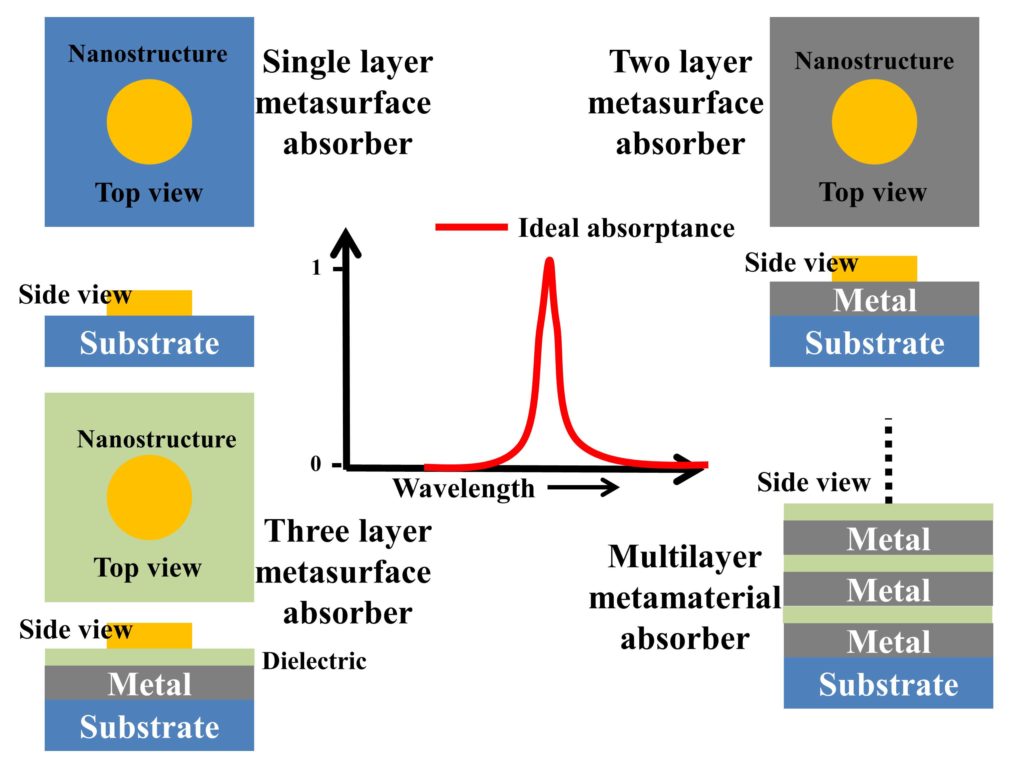
- Antennas can be thought of as absorbers as they need to absorb energy. A known method to make broadband absorbers is to design multiple metamaterial unit elements and arrange them in such a way as to give a broadband absorptance. A similar method can be applied to metamaterial antennas and make UWB metamaterial antenna.
- Metamaterial antennas have smaller dimensions in comparison to their counterpart antennas; therefore, they can be built using less metallic material and therefore, are a cost-effective solution to antennas.
Limitations of metamaterial antennas
- The inclusion of metamaterials in antennas usually results in complex designs, which might be challenging to fabricate. Moreover, the metamaterial designs have smaller dimensions in comparison to the antenna, which adds to the complexity of the design. This limitation curtails the large-scale manufacturing of these metamaterial antennas.
- The optimization of metamaterial antenna designs becomes a difficult task since there are more parameters at work in defining the operational wavelength.
- Since metamaterials are employed along with the antennas, the size of the metamaterial antenna is limited by the dimensions of the antenna.
- Metamaterial antennas can be lossy and may present higher losses than typical antennas.
- The range of metamaterial antennas is somewhat limited.
References
- https://en.wikipedia.org/wiki/Antenna_(radio)
- Dong, Y., & Itoh, T. (2012). Metamaterial-based antennas. Proceedings of the IEEE, 100(7), 2271-2285.
- https://en.wikipedia.org/wiki/Metamaterial_antenna
Further readings
If you liked this post, you might be interested in reading the following.