
Thin film interference
Thin films (sometimes referred to as multilayer coatings) are layers of naturally occurring materials that are deposited in such a fashion that their thickness is small, in comparison to the wavelength of Electromagnetic (EM) waves they manipulate. Thin film interference can be used to calculate the behavior of light when it interacts with the thin film and how the partial reflections and partial transmissions at interfaces interfere with each other to produce either constructive or destructive interference.
Thin film interference of light at the air-water interface
In order to explain the condition of constructive or destructive interference of light (EM wave) in thin films, let us consider an example. In this example, an EM wave of 625 nm (red light) enters from the air into a thin film of water, and then leaves the water into the air as shown in Fig. 1. The reflection and transmission coefficients of EM wave entering material B from material A are given below (with their s-polarization and p-polarization components), respectively.
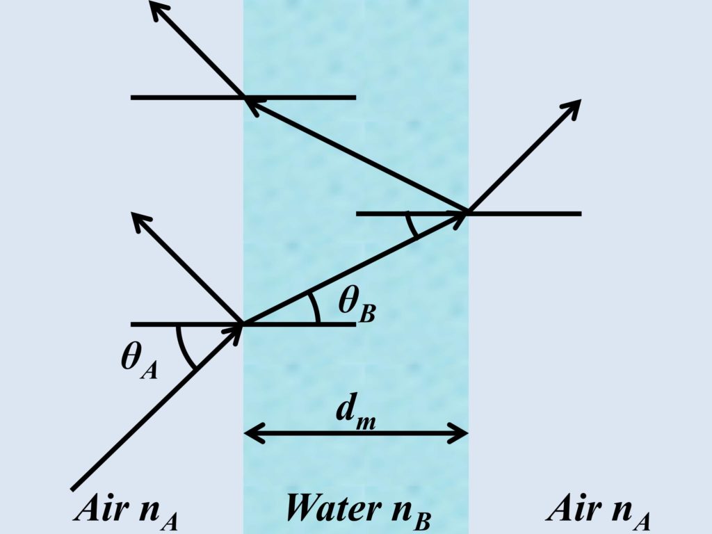
Here nA represents the refractive index of air, θA represents the angle of incidence of EM wave at the boundary between interfaces, nB represents the refractive index of water, and θB represents the angle of refraction at the boundary when a wave enters second material. A simplified version of this problem would be to take EM wave entering the thin film of water at 0˚ from the normal. When an EM wave enters an interface at a normal angle, the angle of refraction is also 0˚. Therefore, the above equations can be simplified into the following.
Moreover, for further simplification, we can only consider reflection and transmission coefficients of s-polarization, and wavelength of EM wave is taken to be 625 nm, where the refractive index of air is ≈1 and refractive index of water is 1.332. The thickness of the water layer is taken to be 234.61 nm. When an EM wave, traveling in the air, meets the boundary of the air-water interface, a portion of it will be reflected and a portion of it will be transmitted, as shown in Fig. 1.
From simplified equations, it can be calculated that reflection and transmission coefficients at air-water interface will be as follows.
Inside the thin film interface, the EM wave will have a change in phase per unit length which is known as propagation constant. The electric field of the EM wave can be shown by the following expression.
{\vec{E}}}={Ee^{-i \beta}}{\vec{E}}}={Ee^{-i \beta}}{\vec{E}}}={Ee^{-i \beta}}
Here, E is the amplitude of EM wave, λ is the wavelength, and dm is the thickness of the thin film (water in this case). The phase accumulation for 234.61 nm comes out to be as follows.
This factor is applied to transmitted wave and then reflection and transmission coefficients of the second interface (water-air) can be calculated.
Now that we have calculated all the coefficients, we can finally calculate the overall reflection and transmission coefficients. A visual depiction of this example is shown in Fig. 2.

For the case of the overall reflection coefficient, one partial reflection coefficient occurs at the first air-water interface, and the second partial reflection coefficient is attained by transmission (air to water)->propagation (water)->reflection (water to air)->propagation (water)->transmission (water to air). To calculate the reflectance and transmittance from the reflection and transmission coefficients, the following formulas can be employed. These formulas can also be used to find absorptance.
In the aforementioned example, the reflectance and absorptance are 0 whereas, the transmittance is 1. This shows that all of the EM wave is transmitted from a thin film of water when the thickness of thin film was kept at 234.61 nm. This signifies that a destructive interference of light is taking place for reflection, thereby, all energy is transmitted. Upon further investigation, it is observed that destructive thin film interference will occur if the propagation phase is equal to π and m multiple of π. This condition is highlighted and further explored below.
The Eq. 13 shows that the left-hand side should be equal to m multiple of wavelength for destructive interference to take place. Similarly, the condition to attain constructive thin film interference of EM wave can be calculated as an odd multiple of following.
Thin film interference can be seen in nature, such as in the case of a soap bubble, a rainbow can be observed due to variation in the thickness of the bubble and variation in the angle of incidence from where that soap bubble is observed.
The theoretical calculations and formulas employed in thin film interference can be used to get an analytical solution one dimensional (1D) and two-dimensional (2D) for EM waves traveling in multilayer coatings (multiparallel interfaces). This is further explained in the post on thin film multilayer coatings.
Further readings
If you like this post, we suggest reading the following posts on closely related topics.


I like the valuable information you provide in your articles. I抣l bookmark your weblog and check again here frequently. I am quite sure I抣l learn many new stuff right here! Good luck for the next!
Thank you very much for your positive feedback. We will try our best to present complex information in a comprehensive and understandable format.
We would love to hear back from you.
You made some good points there. I did a search on the subject matter and found most folks will agree with your blog.
Thank you very much for your comment. We look forward to your feedback in the future as well.
I am really impressed with your writing skills and also with the layout in your weblog. Is this a paid topic or did you modify it yourself? Either way stay up the excellent high quality writing, it抯 rare to see a nice weblog like this one nowadays..
Thank you very much for your comment and positive feedback. This is not a paid topic and we worked on it ourselves.
We look forward to your feedback in the future as well.