Thin Film calculations using matrix method
From our previous discussions on refractive index, and thin film interference, we can now move towards solving a complex system of multiple thin films (or multilayer coatings) and perform thin film calculation as shown in Fig. 1. Thin film calculation can help us to get reflectance and transmittance from the system. The derivation of thin film calculation can be found in multiple textbooks and is, therefore, skipped here. However, each individual entity used in these calculations is explained with sufficient detail. We will use the matrix method to perform this calculation. It is also important to mention that this calculation can also be termed as electromagnetic wave solution that can be used to find 1D EM wave solution (for normal incidence) and 2D EM wave solution (for wave incident at an angle). Consequently, from these calculations, we can develop 1D and 2D EM wave solvers that do not require the use of professional EM wave solvers.

In the matrix method of thin film calculation, we need to solve the following equations for s-polarization and p-polarization, respectively.
For s-polarization, the we need to solve the following equation.
For p-polarization, the we need to solve the following equation.
From the above equation, we will find a matrix A that will be later used to calculate reflectance and transmittance. The tern n represents the refractive index and its subscript denotes the layer. The 0th layer will be the material/medium from which the EM wave is coming from, which is usually air. Similarly, the nth layer is the material/medium where the EM wave will finally enter after passing through multiple thin films. The characteristic of our system of thin films is encoded in matrices M1-MN. The M matrix for each layer is calculated as follows for s-polarization and p-polarization, respectively.
For s-polarization, M matrix can be calculated using the following equation.
For p-polarization, M matrix can be calculated using the following equation.
The term i is the imaginary number iota, and βi is the propagation constant which can be written as (2π/λ)nidi, where ni is the refractive index of the ith thin film and di is the thickness of the same thin film. The M matrix should be calculated for each individual thin film that lies in between 0th and Nth material. These matrices are then multiplied according to Eq. 1 to calculate A matrix.
After the calculation of A matrix, we can obtain the reflection and transmission coefficients of our system, which can be calculated in the same fashion for both s- and p-polarizations.
Reflection coefficient (r), reflectance (R), transmission coefficient (t), transmittance (T), and absorptance (A) are calculated as follows.
Algorithm for thin film calculation (Basis of a 1D/2D solver) using matrix method
- Get refractive indices of different layers at wavelengths of interest.
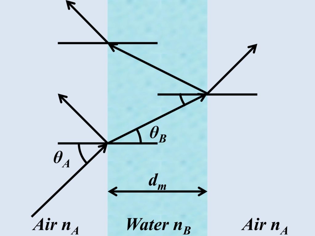
2. Find the angle of refraction for the first thin film as the EM wave enters from material 0 to the first thin film. This angle of refraction can then be used as the angle of incidence for EM wave in thin film 1 to calculate the angle of refraction in thin film 2 and so on. These angles can be calculated using Snell’s law as follows.
3. Find the propagation constant of each thin film.
4. Find the M matrices for each layer.
5. Substitute the values of angle, propagation constants, and M matrices in Eqs. 1 & 2 to calculate the A matrix for each polarization.
6. Calculate reflection coefficient (r), reflectance (R), transmission coefficient (t), transmittance (T), and absorptance (A).
An example of 2d em solver
An example of 2D EM solver is presented here to benefit the reader. In this example, a system of two thin films is solved. The two films are made of glass (SiO2), and Chromium (Cr). A complex refractive index of Cr is taken but for SiO2, a real refractive index of 1.46105 is taken. The initial and final materials are taken to be air, with a refractive index of 1. For simplicity, the EM wave is considered to entering thin film 1 at normal incidence (1D), but, the algorithm (for matrix method) provided here can be used for EM waves traveling at an angle (2D). A Matlab-based algorithm (and its code) for solving such a system is provided below for s-polarization and 50 nm thick SiO2 layer and 150 nm thick Cr layer.
a=xlsread('Cr (n) and (k)',1,'A2:C702');

lam=a(:,1);

n0=complex(1,0);
nN=complex(1,0);
n1=complex(1.46105,0);
n2=complex(a(:,2),a(:,3));

r=zeros(701,1);
Reflectance=zeros(701,1);
t=zeros(701,1);
Transmittance=zeros(701,1);
Absorptance=zeros(701,1);

theta0=deg2rad(0);

for k=1:701
    theta1=asin((n0*sin(theta0))/n1);
    theta2=asin((n1*sin(theta1))/n2(k));
    thetaN=asin((n2(k)*sin(theta2))/nN);

    pc1=(2*pi/(lam(k)*10^-9))*(n1*(50*10^-9)*cos(theta1));
    pc2=(2*pi/(lam(k)*10^-9))*(n2(k)*(150*10^-9)*cos(theta2));

    M1=[cos(pc1) -(1i/(n1))*sin(pc1)*cos(theta1);
    -1i*(n1*sin(pc1))/cos(theta1)  cos(pc1)];
    M2=[cos(pc2) -(1i/(n2(k)))*sin(pc2)*cos(theta2);
    -1i*(n2(k)*sin(pc2))/cos(theta2) cos(pc2)];

    A=(1/(2*n0*cos(theta0)))*[n0*cos(theta0)  1;n0*cos(theta0) -1]*M1*M2*[1  0;n0*(cos(thetaN))  0];

    r(k)=A(2,1)/A(1,1);
    t(k)=1/A(1,1);

    Reflectance(k)=abs(r(k))^2;
    Transmittance(k)=abs(t(k))^2;
    Absorptance (k)=1-Reflectance(k)-Transmittance(k);
end
figure;
plot(lam,Reflectance);
figure;
plot(lam,Transmittance);
figure;
plot(lam,Absorptance);
The file containing the refractive index of Cr is given below.
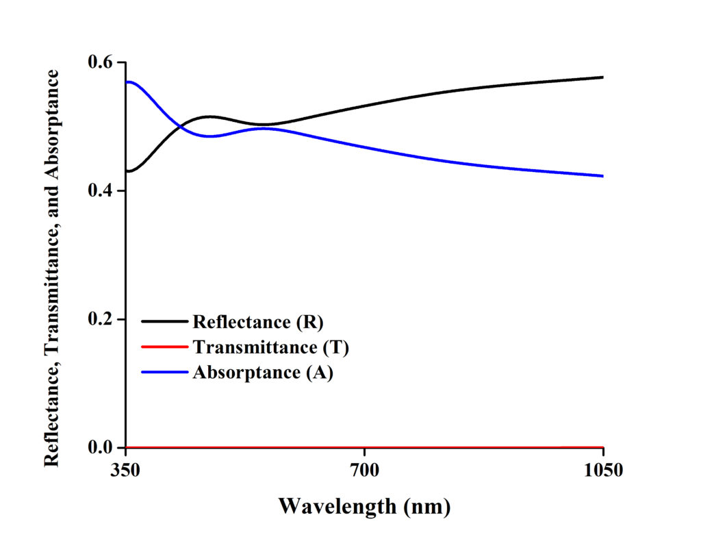
In the code, firstly, the refractive indices SiO2 and Cr are initialized. Then matrices are made for r, R, t, T, and A so that our data can be stored for each wavelength. Since sin and cos commands solve angles in radians, the angle of incidence in degrees is then converted into radians. After that, the angles θ, propagation constants (pc), and M matrices are calculated for each thin film. These values are then subsequently placed in Eq. 1 to get the A matrix, which can be used to calculate the figures of merit reflectance (R), transmittance (T), and absorptance (A). The following curves will be attained in the end.
Further readings
If you like this post, we suggest reading the following posts on closely related topics.