Color filters
A color filter is any object that reflects or transmits light in a way that some color is observed. The color filters, as the name suggests, filters some parts of the electromagnetic spectrum of the sun (or Blackbody radiation spectrum). This wavelength spectrum is then sent to the brain where it is decoded into a color. In order to design color filters, we first need in-depth knowledge of how our eyes behave and what makes them see colors?
How do we see colors with our eyes?
All the objects we see in our daily life can reflect, transmit or absorb light, and almost every object that we see in our daily life has some color associated with it. There are very small cone cells (or photoreceptors) in our eye that are sensitive to some wavelengths. There are three cones cone cells that correspond to the primary colors of red, green, and blue. These cone cells then transmit these signals to the brain where these signals are decoded and the color is perceived within a fraction of a second. The spectral sensitivity curves of different cone cells are presented in Fig. 1 after the red color is received in the eye.
In order to describe the whole process, we take an example of an apple as shown in Fig. 1 and Fig. 2(a). The light falls on the apple and all the other wavelengths except the ones corresponding to the red cone cell are absorbed effectively, while the wavelengths corresponding to the red color are reflected and this spectrum reaches our eye. Now the signals from these cones (or photoreceptors) reach our eye where the color is perceived and indicated by our brain. This makes the apple appear red when light falls on it. Therefore, what we perceive as color, is only a response of our eye that makes it appear as such.
Designing color filters using metasurfaces
To begin our discussion, let us discuss the various types of color primaries. The much more known color primaries are red, green, and blue (RGB). These color primaries are named as such because they are made by mixing two colors of subtractive color primary cyan, magenta, yellow (CMY). The subtractive color primaries are said subtractive because they can be made by subtracting an RGB color from white. These colors are usually employed in printers. Technically these colors can be made by following combinations.
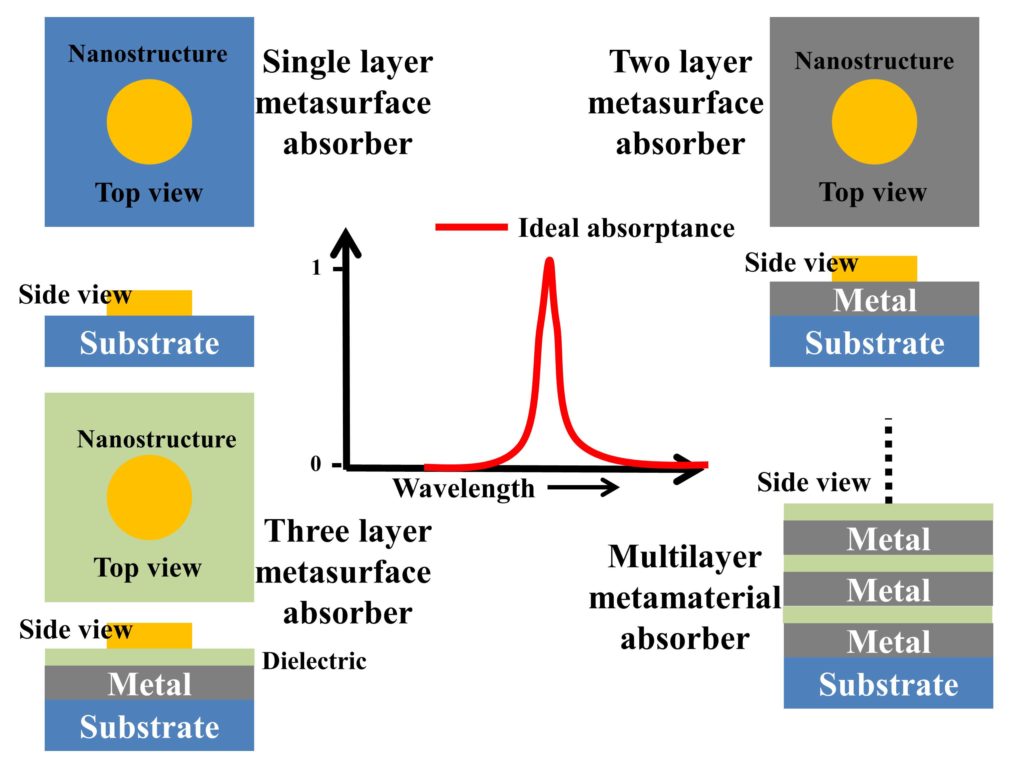
The simplistic color filters can be designed using various materials and their arrangement. The basic type of metasurface, an extremely thin film absorbing layer, can also be employed to make a color filter. There are many different design schemes that can be employed to make thin film color filters. We can use an arrangement of metal-dielectric (where the bottom layer is metal), metal-dielectric-metal, dielectric-metal-dielectric, or any schemes involving multiple thin film layers that can generate a colored response in reflection or transmission.
A simple type of multilayer color filter involves two layer of metal-dielectric, with a metal ground plane to stop transmission and a top thin film layer to vary reflection. This type of color filter reflects a particular color. Analytically designing the color filters is relatively easy due to the availability of algorithms such as the matrix method used to calculate thin film interference. We can vary the thickness of the dielectric layer, which changes the reflection of the design such that the reflectance minimum is shifted from one wavelength to another. Employing such schemes usually produces subtractive colors on the reflection side. The designing of color filters requires optimization, whether analytically or by the use of the software. Now, for example, let us consider, that we attain a reflection curve as shown in Fig. 2(b) from our design.
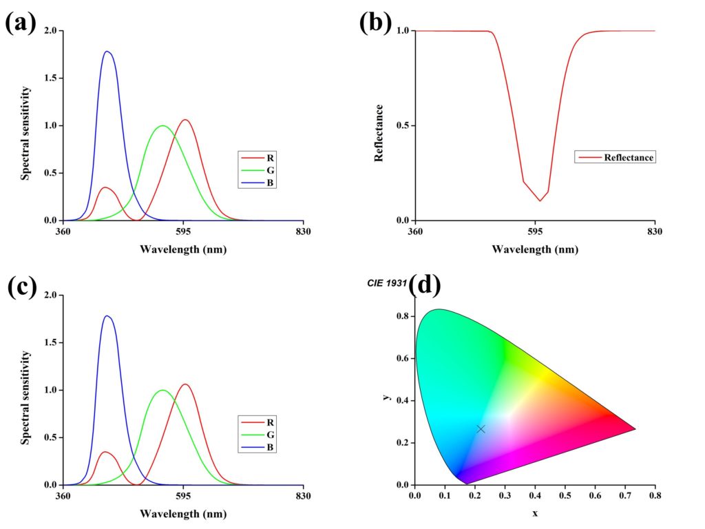
This reflection is almost subtractive where it is subtracting the green color from its result. From Eq. 6, it can be seen that 1-red should give us a cyan color. To calculate the exact color that can be attained from the reflectance curve shown in Fig. 2(b), we should then multiply the reflectance (I(λ)) with tristimulus values of spectral sensitivity (S(λ)) of the eye to obtain Fig. 2(c).
In form of an equation, this relation can be expressed by Eqs. 7-9.
After calculating the aforementioned R(λ), G(λ), and B(λ) curves, we can calculate the Yxy coordinates of CIE 1931(Commission Internationale de l’Elcairage-CIE) to check which color will be observed. A CIE 1931 plot is readily available online and can be obtained. In order to find x, y coordinates on CIE 1931 plot, we first need to find X, Y, and Z. The X, Y, and Z are summations of R, G, and B, respectively in the visible regime, as shown in the following equation.
The X, Y, and Z values of the reflectance curve shown in Fig. 1(a) are X=45.4663, Y=54.9364, and Z=106.4195. Now x, y coordinates can be calculated for CIE 1931 plot by following formulas.
Finally, the calculated x and y coordinates for the same reflectance curve are obtained as x=0.21983 and y=0.2656. These coordinates are plotted in Fig. 2(d) for reference, which shows a cyan color (cross marker).
Steps involved
- Get an optimized reflection/transmission from design.
- Calculate the corresponding R(λ), G(λ), and B(λ) curves from the curve.
- Calculate X, Y, and Z values.
- Calculate x and y coordinates for CIE 1931 plot.
Designing the color filters
The basic step of designing and optimizing the color filters was kept for last. To optimize the structure we need to calculate pure color coordinates for CIE 1931. Usually, the colors in the RGB scheme are represented by three coordinates, each representing R, G, and B values, for example, a value of (1, 0, 1) will show full intensity R and B colors with 0 G. The combination of R and B colors will give pure magenta color. In order to go from these RGB values to CIE 1931 coordinates, the following matrix can be employed.
After calculating X, Y, and Z values, we can employ Eqs. 13-14 to calculate CIE 1931 coordinates.
References
- Rana, A. S., Zubair, M., Anwar, M. S., Saleem, M., & Mehmood, M. Q. (2020). Engineering the absorption spectra of thin film multilayer absorbers for enhanced color purity in CMY color filters. Optical Materials Express, 10(2), 268-281.
Further readings
If you liked this post, you may be interested in the following closely related posts.